Solenoid Symbol Electrical Schematic
solenoid valve symbol p&id Solenoid valve symbols
Intelligent symbols; Electrical schematics; Quick demo video; Education plan; CEX Professional; Capital Electra 2210; The offline version; Download Capital Electra 2210; COMPANY; Our story; Blog; News and media; Careers; Customers and Testimonials; Contact us; RESOURCES; Electrical Symbols; JIC / NFPA Sample Drawing; IEC 60617 Sample Drawing; P.
Chapter 3 electro pneumatic.updated
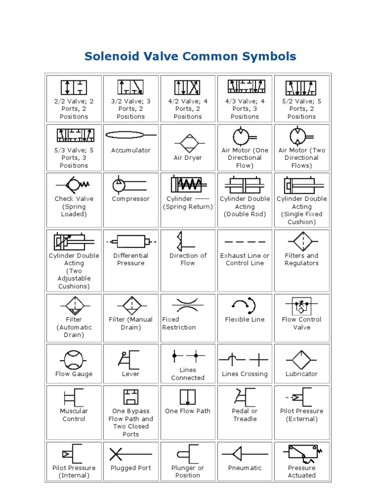
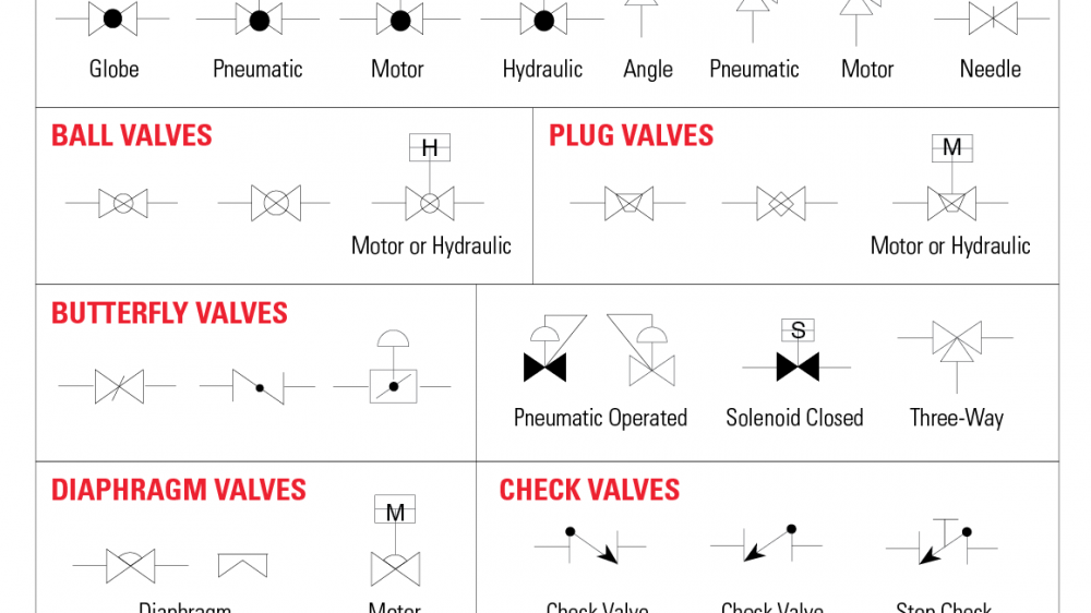
Solenoid Valve Symbols: The following symbols are generally in accordance with BS1553-1 and BS5070 Different Line Types. Pipe Support Symbols Symbols for fitting and representations. Symbols for Valves Symbols for Valve Actuators Symbols for Instruments Symbols for Flow Instruments Instrument Indentifiers
Solenoid valve symbol icon Royalty Free Vector Image
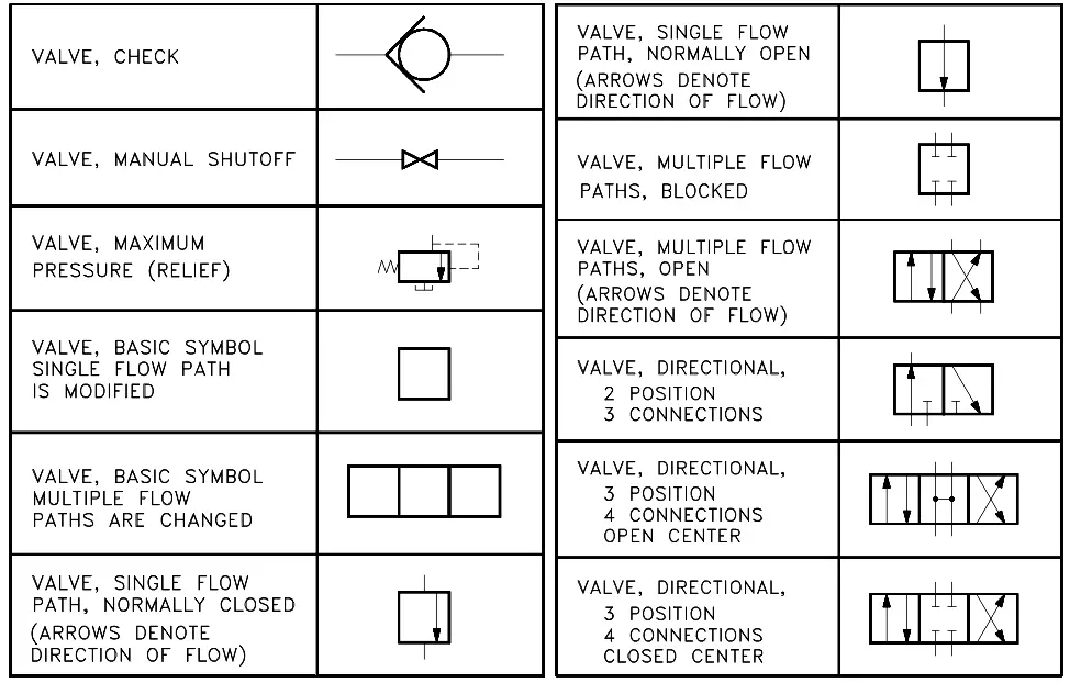
Schematic symbols are used to identify and graphically depict the function of fluid power components. Recognizing and understanding schematic symbols will enable you to comprehend a circuit's function. Schematic drawings document the machine logic only and are never to be used as a piping diagram. All pneumatic circuits consist of valves.
solenoid valve symbol electrical Valve solenoid symbols fixed
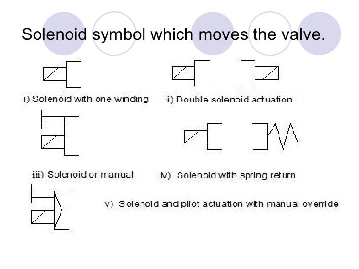
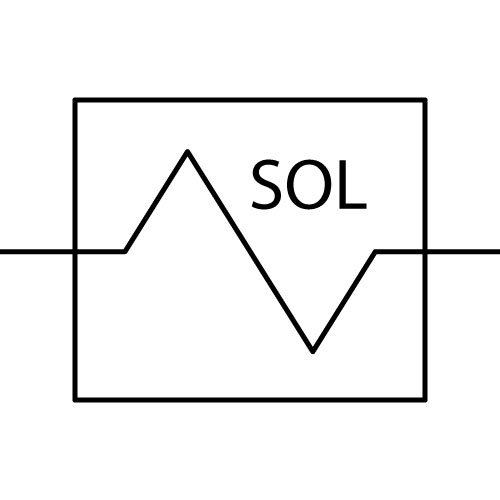
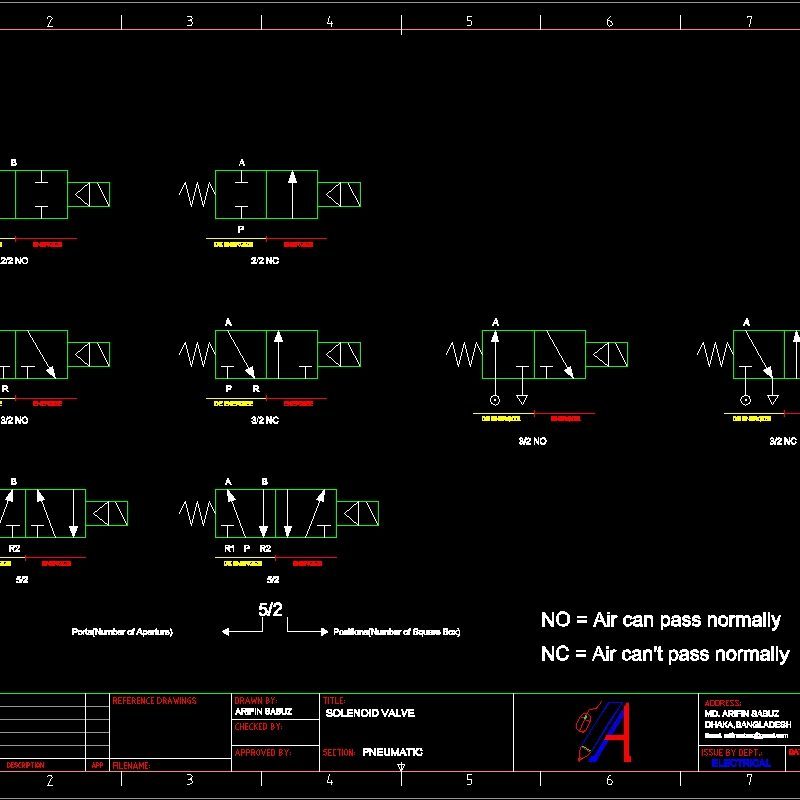
The symbol for the solenoid or the pressure-operated valve has the same number of squares as the valve has positions. The right-hand square shows the valve in its non-actuated (rest) position, the left-hand square corresponds to a valve in its actuated (work) position. 2 positions 3 positions Function: NC = normally closed (rest position)

Solenoid Symbol Electrical Schematic
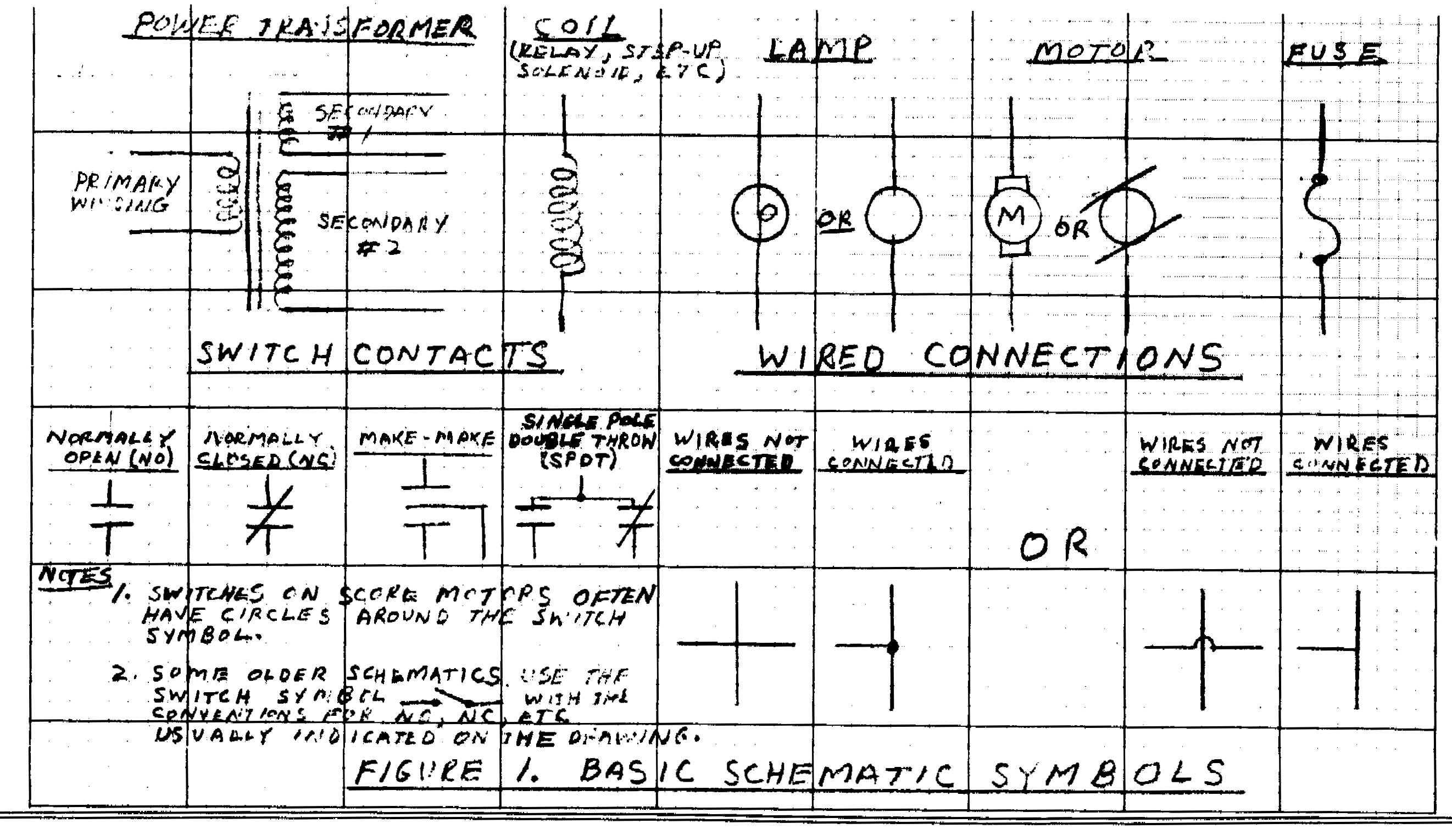
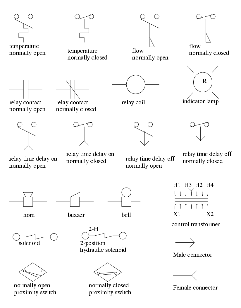
Electrical & electronic symbols and images are used by engineers in circuit diagrams and schematics to show how a circuits components are connected together. Circuit layouts and schematic diagrams are a simple and effective way of showing pictorially the electrical connections, components and operation of a particular electrical circuit or system.
Ferrite Core Inductor Symbol
Electrical symbols & electronic circuit symbols of schematic diagram - resistor, capacitor, inductor, relay, switch, wire, ground, diode, LED, transistor, power supply, antenna, lamp, logic gates,.
Master Symbol Register
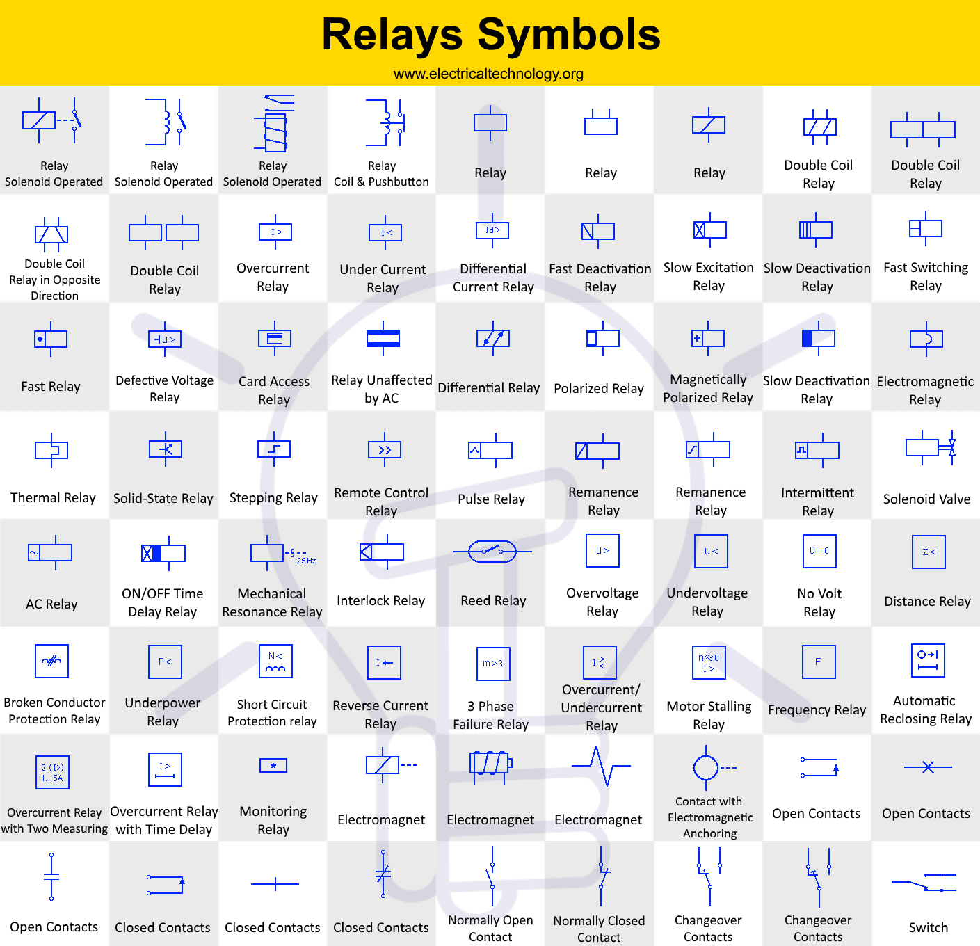
The solenoid operated relay has a coil wound around a core that produces magnetic field when the coil is energised by the current flowing through it. The magnetic field pulls the lever (movable contact) to either make or break the contact. Solenoid Relay with Pushbutton This relay has a push button instead of a lever.
Circuit, diagram, electric, electronic, solenoid operated relay icon
ELECTRICAL SYMBOLS INDICATORS & ALARMS RELAYS ELEMENTARY DIAGRAM CONNECTIONS WIRE NUMBERING ABBREVIATIONS ANSI/IEEE Standard Device Numbers - Master Element - Time Delay Starting or Closing Relay - Checking or Interlocking Relay - Master Contactor - Stopping Device - Starting Circuit Breaker - Rate of Change Relay
solenoid valve symbol p&id Solenoid valve symbols
A "solenoid" is nothing more than a coil of wire designed to produce a magnetic field when energized. Solenoid actuators work by attracting a movable ferrous armature into the center of the solenoid coil when energized, the force of this attraction working to actuate a small valve mechanism.
️Relay Wiring Diagram Symbols Free Download Goodimg.co
that electrical control equipment be located in one area while the load device is located in another. Solenoids, contactors, and magnetic motor starters are used for remote control of devices. Solenoids A solenoid is an electrical device that converts electrical energy into a linear mechanical force. Electric Motor Controls, G. Rockis, 2001
Electrical Schematic Symbol For Solenoid
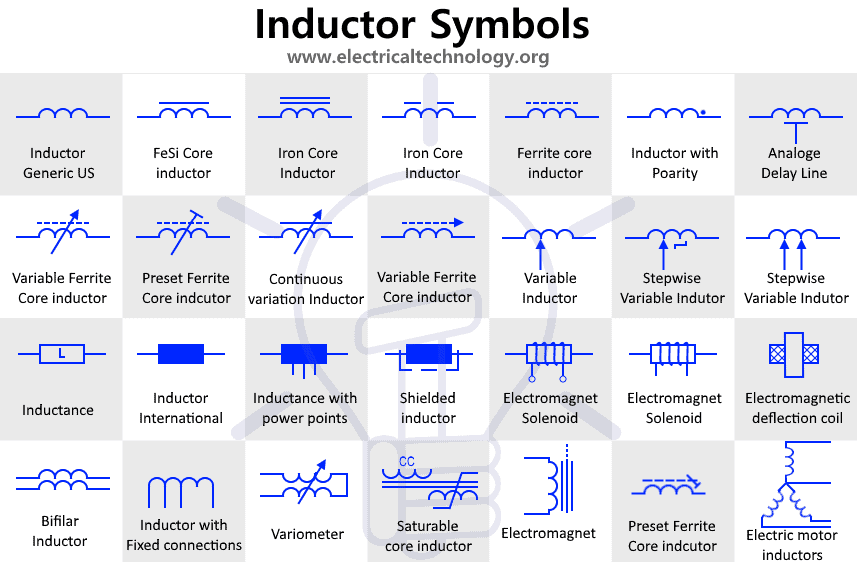
Inductor Symbols - Coils and Choke Symbols Generic Fixed Inductor This is the symbols used for representing a generic Inductor whose inductance value is fixed. An inductor is also known by many names such as coil , choke etc. stores energy inside magnetic field. Variable Inductor This type of inductor has variable inductance.
Simbologia Cad Simu
Here is a brief breakdown of how to read a symbol. Pneumatic Circuit Valve Symbols Most valve symbols have three parts (see Figure 2A below). The Actuators are the mechanisms which cause the valve to shift from one position to another. The Position and Flow Boxes indicate how the valve functions.

Solenoid Symbol Electrical Schematic
The solenoid valve symbols constitute of the box, arrow, "T" and characters. The meaning of the solenoid valve symbols is as below. 1. Use the box to indicate the working position of the solenoid valve. Every box indicates one working position of the solenoid valve, namely "position". The number of positions are decided by the number of boxes.
Electrical Schematic Symbol For Solenoid
A solenoid ( / ˈsoʊlənɔɪd / [1]) is a type of electromagnet formed by a helical coil of wire whose length is substantially greater than its diameter, [2] which generates a controlled magnetic field. The coil can produce a uniform magnetic field in a volume of space when an electric current is passed through it.
Hydraulic Solenoid Valve Symbols
The solenoid is a type of electromagnet, the purpose of which is to generate a controlled magnetic field through a coil wound into a tightly packed helix. The solenoid is as shown in the figure below. The solenoid is a coil of wire, and the plunger is made of soft iron.
Mechanical Drawing Symbols Mechanical Engineering Mechanical
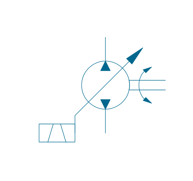
The first operator is the symbol for a solenoid coil that magnetically pushes on the armature pin, which makes sense as the diagonal line leans towards the valve body.
